Published 24 December 2025 · Updated 24 July 2026
· 12 min read
Common Mistakes to Avoid When Installing an E‑Bike Conversion Kit
Unlock £10 Off Today
kirbEbike10
Copy successful
Avoid common e-bike conversion mistakes with compatibility checks, torque-arm guidance, brake and battery checks, plus a six-step test before first power-on.
A reliable e-bike conversion starts before the first bolt is tightened. Most avoidable problems come from buying an incompatible kit, seating the motor axle incorrectly, omitting torque protection, mounting the battery poorly or powering the system before the safety checks are complete.
Installation mistakes: the quick answer
Before ordering, confirm wheel size, dropout spacing and material, axle fit, brake type, drivetrain standard and battery clearance. During installation, seat the axle fully, use the required anti-rotation hardware or torque arm, secure every cable away from moving parts and test the brake cut-offs before a low-power first ride.
Complete the mechanical and electrical checks before applying full power.
Compatibility checklist before you buy
Check
What to confirm
Why it matters
Wheel and brake
Wheel diameter, rim width, tyre clearance and disc or rim-brake compatibility
The wrong wheel or rotor position can make safe brake setup impossible
Dropouts
Inside spacing, slot width/depth, material and condition
The axle must sit fully and squarely without forcing or spreading a damaged frame
Axle and torque control
Axle flats, tab washers and the correct torque-arm arrangement
Motor torque can rotate the axle and damage the dropout
Drivetrain
Freewheel or cassette, gear count, chain line and derailleur clearance
These systems are not interchangeable and may need different hub hardware or spacing
Battery fit
Frame clearance, mounting points, cable exit and removal space
A battery must be supported securely and remain removable without contacting the frame
Electrical match
Battery voltage, controller limits, connector types, display and charger
Mismatched voltage or pinouts can prevent operation or damage components
Braking condition
Pads, cables or hoses, rotors/rims and brake cut-offs
Added mass and speed require predictable stopping performance
Before power-on: 6 checks
Check fit: confirm the wheel is centred, the tyre clears the frame or fork and the brake can be aligned.
Seat the axle: make sure both axle flats sit fully in the dropouts before tightening.
Fit torque protection: install the supplied anti-rotation washers and the specified torque arm; never rely on axle nuts alone on a high-torque setup.
Secure the battery: tighten the mount, support the weight and check that the pack cannot shift or release over bumps.
Route cables: keep wiring clear of the chain, crank, tyre, rotor and steering pinch points, leaving enough slack for full handlebar movement.
Test safety functions: lift the driven wheel, confirm correct rotation, verify the brake cut-offs and begin with the lowest assistance or power setting.
Fast fault-finding after installation
Symptom
Likely checks
First action
Motor does not run
Battery switch, display, main connector, brake cut-off and connector arrows
Power off, reseat one connector at a time and inspect for bent pins
System cuts out under load
Battery charge, voltage match, loose power connector or protection limit
Stop testing at high power and verify the electrical ratings
Axle nut loosens or dropout marks appear
Axle seating, washers, torque arm and fastener torque
Stop riding immediately and correct the mechanical installation
Brake rubs after wheel installation
Wheel centring, rotor position, spacers and caliper alignment
Re-centre the wheel before adjusting the brake
Shifting is poor
Freewheel/cassette type, gear spacing, chain line and derailleur indexing
Confirm drivetrain compatibility before adding spacers
Cable pulls when steering
Harness length, tie placement and fork/handlebar movement
Re-route with enough slack for full steering travel
If any safety-critical fit is uncertain, stop and have the bicycle inspected by a qualified mechanic. You can also compare KirbEbike’s conversion kits and compatible batteries before choosing a system.
Understanding Installation Success
Thebest ebike kit systems include everything needed for successful installation: motor, battery, controller, display, sensors, hardware, tools, and comprehensive instructions. However, installation success depends equally on following proper procedures and avoiding common pitfalls that compromise the system.
Why Installation Quality Matters
Critical Pre-Installation Mistakes
Mistake #1: Not Reading Instructions Completely
The Error: Many installers jump straight to physical installation without thoroughly reviewing all documentation, videos, and resources provided.
Why It's Problematic:
Miss critical preparation steps
Overlook compatibility warnings
Skip essential safety procedures
Waste time backtracking
Risk component damage
The Solution:
Before touching any components:
Watch entire installation video start to finish
Read complete instruction manual
Review all included documentation
Check manufacturer's website for updates
Join online community for tips
Preparation Checklist:
✓ Understand complete process flow
✓ Identify all components and their functions
✓ Note any bike-specific considerations
✓ Gather all required tools
✓ Prepare adequate workspace
✓ Allow sufficient time without rushing
Mistake #2: Inadequate Workspace Preparation
The Error: Beginning installation in cramped, poorly lit, or unsuitable locations without proper organization.
Problems Created:
Lost small components
Difficulty accessing bike areas
Poor visibility for connections
Frustration and errors
Extended installation time
The Solution:
Ideal Workspace Setup:
Clean, well-lit area with adequate space
Bike repair stand or secure mounting
Flat surface for organizing components
Good lighting from multiple angles
All tools within easy reach
Component trays or containers for small parts
Organization Strategy:
Lay out all kit components systematically
Verify everything against packing list
Group related components together
Keep fasteners organized by type
Have camera ready for documentation
Mistake #3: Wrong Tool Selection
The Error: Attempting installation with inappropriate, low-quality, or incorrectly sized tools.
Consequences:
Stripped fasteners
Damaged components
Rounded bolt heads
Improper torque application
Personal injury risk
The Solution:
Essential Tools Required:
Hub Motor Installation:
Quality Allen key set (4mm, 5mm, 6mm)
Adjustable wrench or pedal wrench (15mm)
Cassette removal tool (included with kit)
Chain whip (included with kit)
Tire levers
Torque wrench (recommended)
Cable ties and cutters
Electrical tape
Mid-Drive Installation:
All hub motor tools plus:
Bottom bracket removal tool
Crank puller tool
Additional Allen keys for crank bolts
Tool Quality Matters:
Use proper-sized tools only
Avoid rounded or worn tools
Invest in quality Allen keys
Consider torque wrench for critical fasteners
Replace damaged tools immediately
Motor Installation Mistakes
Mistake #4: Incorrect Wheel Orientation
The Error: Installing motor wheel backwards or with cables routed incorrectly.
Problems This Creates:
Motor cable too short to reach controller
Brake rotor on wrong side
Tire rotation direction incorrect
Cable stress and potential damage
Difficult cable management
The Solution:
Proper Hub Motor Orientation:
For rear wheel motors:
Motor cable exits on non-drive side (left side)
Check cable length before full installation
Verify brake rotor position matches caliper
Confirm cassette threads onto motor properly
Mistake #5: Missing or Improperly Installed Torque Arms
The Error: Omitting torque arms entirely or installing them incorrectly—one of the most dangerous installation mistakes.
Why This Is Critical:
Torque arms prevent motor axle rotation under power by:
Transferring motor torque to frame
Preventing dropout damage
Protecting frame integrity
Ensuring safe operation
Frame Damage Risk:
Aluminum frames especially vulnerable
Dropouts can crack or deform
Frame failure possible under power
Dangerous sudden failures
Expensive frame replacement
The Solution:
Proper Torque Arm Installation:
Minimum Requirements:
One torque arm for motors under 750W
Two torque arms for motors 1000W and above
Both sides for high-power systems (2000W+)
Installation Procedure:
Clean dropout area thoroughly
Position torque arm flush against dropout
Insert through axle
Connect to frame or fork
Tighten all fasteners to specification
Verify no movement possible
Recheck after first ride
Mistake #6: Improper Axle Tightening
The Error: Over-tightening or under-tightening motor wheel axle nuts.
The Error: Mounting battery where it interferes with riding, creates imbalance, or risks damage.
Problems Created:
Knee interference while pedaling
Poor weight distribution
Cable strain
Difficult battery removal
Increased damage risk
The Solution:
Optimal Battery Placement:
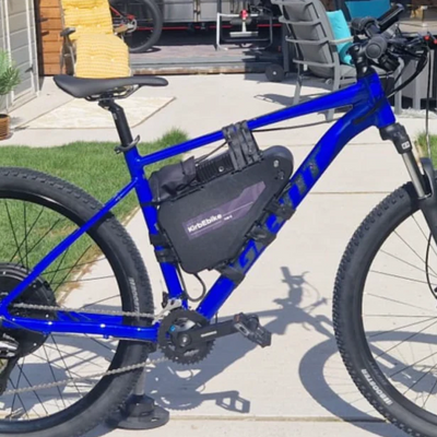
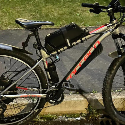
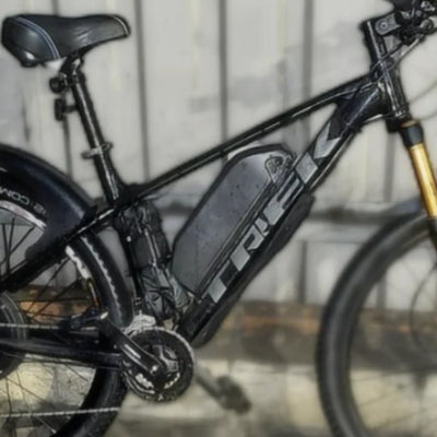
Down Tube Mounting (Most Common):
Center of gravity low and central
Easy access for removal
Protected from impacts
Cable routing straightforward
Doesn't interfere with riding
Installation Best Practices:
Use all provided mounting bolts
Verify bottle cage holes alignment
Check pedal clearance (especially at full lock)
Ensure cable can reach without tension
Test battery removal/installation ease
Confirm lock mechanism functions
Mistake #8: Neglecting Cable Management
The Error: Leaving cables loose, unsecured, or routed where they can snag, rub, or get damaged.
Consequences:
Cable wear from rubbing
Snagging on obstacles
Water ingress at connections
Unprofessional appearance
Potential short circuits
Safety hazards
The Solution:
Professional Cable Management:
Routing Principles:
Follow natural frame lines
Avoid moving parts (cranks, wheels)
Prevent rubbing on tire
Keep away from heat sources
Allow handlebar turning clearance
Protect from water spray
Mistake #9: Reversed Motor Cable Connections
The Error: Connecting motor phase wires in wrong sequence, causing motor to run backwards or inefficiently.
Symptoms:
Motor runs opposite direction
Reduced power output
Controller errors
Abnormal noises
Poor performance
The Solution:
Proper Connection Procedure:
Most modern systems use keyed connectors preventing incorrect connection, but if issues arise:
Diagnosis:
Power system and test throttle
Observe wheel rotation direction
Check for error codes on display
Verify smooth operation
Correction (if needed):
Disconnect motor phase wires
Swap any two of three phase wires
Test operation
If still incorrect, try different combination
Secure properly once correct
Display and Control System Mistakes
Mistake #10: Incorrect Sensor Installation
The Error: Improperly installing or aligning pedal assist sensor (PAS) or failing to secure properly.
Problems This Creates:
No pedal assist function
Inconsistent assist activation
Delayed motor response
Assist remains on constantly
Premature component wear
The Solution:
Cadence Sensor Installation:
Disc-Type PAS:
Mount sensor bracket on left crank side
Position sensor head near bottom bracket
Install sensor disc on crank arm or pedal spindle
Align with 2-3mm gap between disc and sensor
Secure all fasteners
Test rotation—no rubbing
Magnet-Type PAS:
Install sensor on chainstay
Mount magnet on crank arm
Align for proper gap (typically 5mm)
Verify clearance throughout pedal rotation
Test sensor detection
Mistake #11: Display Mounting Issues
The Error: Mounting display where it's difficult to read, interferes with controls, or is vulnerable to damage.
Consequences:
Poor visibility while riding
Difficult button access
Cable strain
Collision with knees
Weather exposure
The Solution:
Optimal Display Placement:
Position Criteria:
Easily visible while riding
Buttons accessible without hand repositioning
Doesn't interfere with brake/shift levers
Protected from direct impact
Cable reaches without tension
Secure mounting
Mistake #12: Brake Sensor Omission
The Error: Failing to install brake cut-off sensors or installing them incorrectly—a serious safety issue.
Safety Risk: Motor continues running when braking, causing:
Extended stopping distances
Loss of control
Brake system overload
Accident risk
Legal liability
The Solution:
Mandatory Brake Sensor Installation:
Installation Procedure:
Remove existing brake levers (if replacing)
Install new levers with integrated sensors
Connect brake sensor cables to controller
Adjust lever reach for comfort
Route cables cleanly
Test extensively before riding
Verification Testing:
Power system on
Engage throttle or pedal assist
Pull brake lever
Motor should cut immediately
Test both front and rear
Verify quick response
Critical Safety Check:
Test at low speed initially
Verify instant motor cutoff
Check both brakes independently
Test in various assist levels
Confirm consistent operation
Electrical System Mistakes
Mistake #13: Ignoring Waterproofing
The Error: Failing to properly seal electrical connections or exposing components to water intrusion.
Long-Term Consequences:
Corrosion of connections
Intermittent failures
Short circuits
Component damage
Fire risk
The Solution:
Waterproofing Best Practices:
Connection Protection:
Ensure all connectors fully engaged
Verify rubber seals properly seated
Apply dielectric grease to connections
Use electrical tape on suspect areas
Position connectors away from direct spray
Route cables to drain water away
Component Positioning:
Controller in protected location
Battery connectors facing down when possible
Display angled to shed water
Sensors protected from direct spray
Maintenance:
Inspect connections regularly
Clean and reapply dielectric grease annually
Replace damaged connector seals
Check for corrosion
Address any water ingress immediately
Pre-Ride Testing Checklist:
Test
Procedure
Pass Criteria
Power On
Turn on battery and display
Display illuminates, no errors
Throttle
Lift rear wheel, test throttle
Smooth acceleration, proper direction
Brake Cutoffs
Engage motor, pull brakes
Instant motor cutoff both sides
Pedal Assist
Pedal forward in each level
Smooth engagement, appropriate power
Display Functions
Check all buttons and menus
All functions respond correctly
Battery Reading
Verify charge level display
Accurate indication
Lights
Test headlight and brake light
Proper operation if equipped
Sensors
Verify all sensor functions
Proper detection and response
Initial Ride Testing:
Start in safe, open area
Test low assist levels first
Verify braking effectiveness
Check handling changes
Test all assist levels progressively
Verify range estimation
Check for unusual noises
Monitor battery consumption
Mistake #16: Ignoring Torque Specifications
The Error: Guessing at proper tightness instead of following specified torque values.
Component Risk:
Critical Fasteners:
Motor axle nuts
Torque arm bolts
Battery mounting bolts
Crank bolts (mid-drive)
Bottom bracket (mid-drive)
Cassette lockring
The Solution:
Torque Specification Guidelines:
While specific values vary by component:
General Ranges:
Motor axle nuts: 35-40 Nm typical
Torque arm bolts: 15-20 Nm typical
Battery bolts: 5-8 Nm typical
Crank bolts: 35-40 Nm typical
Cassette lockring: 40 Nm typical
Best Practices:
Invest in quality torque wrench
Follow manufacturer specifications exactly
Tighten in proper sequence
Recheck after first 50km
Document all torque values applied
Compatibility and Braking Mistakes
Mistake #14: Choosing the Wrong Dropout, Wheel or Drivetrain Type
The error: Ordering a conversion wheel based only on wheel diameter without checking the bicycle’s dropout width, axle fit, brake system or rear drivetrain.
A 26-inch or 700C label does not confirm compatibility by itself. Before installation, measure the inside dropout spacing and confirm whether the bike uses a front or rear wheel, disc or rim brakes, and a threaded freewheel or cassette system.
Measure dropout width with the wheel removed.
Confirm the required wheel diameter and tyre clearance.
Identify freewheel versus cassette before ordering.
Check rotor mounting, brake clearance and cable routing.
Never force a motor axle into dropouts that do not match.
If any measurement is unclear, photograph the dropout and drivetrain and confirm compatibility before installation.
Mistake #15: Leaving the Original Brakes Unchecked on a High-Power Build
The error: Increasing motor power, system weight and potential speed without checking whether the existing brakes, tyres and wheels remain suitable.
Higher-power conversions place greater demands on braking and handling. Inspect pad or rotor wear, brake alignment, tyre condition, spoke tension and wheel trueness before the first powered ride. Replace worn components and use equipment appropriate for the intended riding environment.
Test both brakes before connecting motor power.
Confirm brake cut-off sensors operate correctly where fitted.
Start with the lowest assist level in a controlled area.
Recheck axle nuts, torque arms, brakes and spokes after the first rides.
Conclusion
Avoiding these common installation mistakes ensures your e-bike conversion delivers safe, reliable, high-performance electric assistance for years. The 20-minute hub motor or 30-40 minute mid-drive installation becomes straightforward when you prepare properly, follow instructions carefully, and take time to do each step correctly.
Qualitymid motor electric conversion kit systems from reputable manufacturers include everything needed for success—but installation quality determines actual performance and longevity.
Frequently Asked Questions
What's the most critical mistake to avoid when installing an e-bike conversion kit?
Missing or improperly installing torque arms represents the most dangerous mistake, risking frame damage and sudden failure. Always install minimum one torque arm for motors under 750W, two for 1000W+ systems. Verify they're secured properly and cannot rotate—this single component prevents thousands in frame damage and serious safety hazards.
How tight should motor axle nuts be?
Follow manufacturer torque specifications (typically 35-40 Nm) using a torque wrench. Over-tightening damages dropouts and bearings, while under-tightening allows movement causing brake issues and safety hazards. Tighten gradually alternating sides, verify wheel centering, and recheck after 50km of riding for optimal security.
Do I really need to install brake cut-off sensors?
Absolutely—brake sensors are mandatory safety components that instantly cut motor power when braking. Without them, the motor continues running while braking, extending stopping distances dramatically and creating dangerous loss of control scenarios. Test both brake sensors thoroughly before riding to verify instant motor cutoff.
What's the correct gap for pedal assist sensors?
Maintain 2-3mm gap between disc-type PAS sensor head and sensing disc. Too close causes rubbing and sensor damage, too far prevents detection and eliminates pedal assist. Verify clearance throughout complete pedal rotation, secure all mounting hardware, and test sensor response before riding.
How do I know if my cables are routed correctly?
Proper cable routing follows natural frame lines, avoids moving parts (wheels, cranks), prevents rubbing on tires, allows handlebar turning clearance, and secures every 15-20cm with cable ties. Verify no tension on connections, protection from water spray, and professional appearance. Test full handlebar movement before riding.
Should I test the system before my first ride?
Comprehensive pre-ride testing is essential: lift rear wheel and test throttle for proper rotation, verify both brake sensors cut motor instantly, test all pedal assist levels, check display functions, ensure no unusual noises, and verify battery readings accurate. Initial ride should be in safe, traffic-free area testing progressively.
What should I do if I make a mistake during installation?
Stop immediately, don't force anything, and refer to instructions or videos. Disassemble back to last known good state, identify the error, correct it properly, and proceed systematically. Contact manufacturer support if uncertain—better to ask than damage components or create safety hazards. Document issues for future reference.