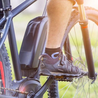
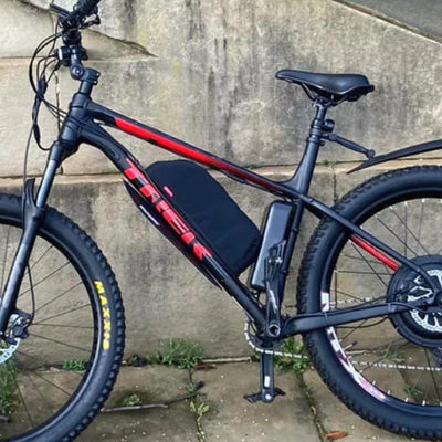
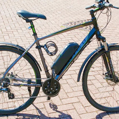
A hub motor drives the wheel forward and pushes back on its own axle with equal force. That reaction torque is what spreads dropouts, spins axles and severs motor cables on high-power builds — and it’s why torque arms exist. Whether you need one arm, two, or a custom plate is decided by measured torque, axle fit, dropout strength and regenerative braking — never by the wattage on the box. This guide covers how torque arms work, when one is enough, when two are needed, and how to mount them safely on 1000W–4000W hub motors.

A torque arm moves the axle’s reaction force away from the small dropout slot and into a larger, stronger part of the frame. Wattage alone cannot tell you how many you need. A 1000W rear motor on thick steel dropouts with no regen, a tight axle-plate fit and an approved single-arm setup may be fine with one engineered arm. A 2000W–4000W build, a front hub, aluminium dropouts, cargo loads or regenerative braking should trigger an engineering review of that specific motor, controller, frame and braking setup. Two thin, loose arms are not automatically safer than one properly fitted heavy-duty arm — and no torque value, washer order or mounting direction should ever be copied from one motor to another.
What Does an Ebike Torque Arm Do?
A torque arm is an anti-rotation component that fits over the flat-sided motor axle and anchors to the frame or fork. It does two jobs: it stops the axle rotating in the dropout, and it transfers reaction torque into a stronger area of the frame. It is not a wheel-retention device — do not rely on it to hold the wheel if axle-nut clamping force is lost.
The physics is simple. The motor turns the wheel forward, so the axle pushes back with equal force. The axle flats press against the dropout sides, and repeated loading can spread, crack or deform them. A torque arm increases the distance between the axle and the point where that force is resisted. The numbers are bigger than most riders expect: a 12mm axle producing 40 N·m exerts a spreading force of just under 1,000 lb on each dropout — which is exactly why motor wattage alone does not describe the mechanical load.
Torque washer vs torque arm vs torque plate
A torque washer is a small tab engaging the dropout — limited local support, heavily dependent on correct seating, and no substitute for an engineered arm on a high-power build. A torque arm extends the reaction point away from the axle and anchors via a clamp, eyelet, bolted plate or custom mount. A torque plate is usually a larger or custom plate fixed around the dropout area, suiting high measured torque, unusual geometry, regen, or dropout faces needing reinforcement. Don’t treat any of these names as proof of strength — construction and fit matter more.
Why Wattage Alone Cannot Determine Torque-Arm Requirements
Plenty of guides claim one arm is always enough below some wattage and two are mandatory above it. That is an oversimplification, and it can be wrong in both directions.
Electrical input power vs mechanical axle torque
Motor input power is voltage × current. Mechanical power is torque × angular velocity. So a low-speed motor can produce substantial axle torque at modest wattage, while a high-speed motor can show a bigger wattage figure without proportionally higher starting torque.
Nominal power vs peak power
A kit marketed as 1000W may draw well over that under acceleration, and a 3000W motor on a lower-current controller may not load the axle as hard as another 3000W system. Assess these separately: nominal rating, battery current limit, controller phase current, peak electrical input, measured motor torque, and regen torque.
One related myth: axle reaction torque comes from the motor itself, so wheel diameter changes the force at the tyre and the resulting acceleration — but a bigger or smaller wheel never makes a weak dropout safe.
- Controller battery current limit and phase current
- Published or measured peak axle torque (N·m)
- Axle diameter and distance across the flats
- Whether regenerative braking is enabled
- The engineer-approved arm setup for that exact variant
When Is One Torque Arm Enough?
One high-quality torque arm may be sufficient when the complete installation has been technically reviewed and all of the following hold true:
- Rear hub motor rather than a front motor
- No regenerative braking
- Strong, undamaged dropouts with full axle engagement on both sides
- Axle plate fits the flats with minimal play
- Arm is thick enough and approved for the measured load
- Arm anchors to a strong frame location, and axle nuts have adequate thread engagement
- Motor cable is protected and fasteners can be inspected easily
- The manufacturer explicitly permits a single-arm setup
This is why the part matters more than the count. Grin notes one of its thick arms is often sufficient, while thinner third-party arms may need doubling up — evaluate the actual component, not just the motor’s wattage.
Rear motor vs front motor
Rear dropouts are commonly thicker and better supported than front forks. Even so, a rear motor can still spread shallow or damaged dropouts, and a front-wheel failure causes immediate loss of steering and wheel retention. A front hub needs a fork-specific assessment regardless of wattage.
Steel vs aluminium dropouts
Steel usually deforms before it fractures, but still needs correct axle and washer fit. Aluminium is more sensitive to local stress and poor washer seating, and may crack rather than visibly spread — it deserves a more conservative assessment. Aluminium and carbon frames should never be cold-set or re-spaced to make a motor fit. Steel does not make a torque arm optional by default.
When Are Two Torque Arms Needed?
Two arms can share load and add redundancy — but only when both are installed correctly. Consider dual arms when the build includes any of the following:
- High measured starting torque, or a 2000W–4000W system
- High controller phase current
- Aluminium dropouts, or shallow dropout engagement
- Cargo use, heavy total load, or repeated steep hill starts
- Hard off-road use, or regenerative braking
- Any previous dropout movement
- Thin third-party torque arms, or no suitable single-arm anchor point
- A manufacturer specification calling for dual-arm retention
One heavy-duty arm vs two thin arms
| Factor | One engineered heavy-duty arm | Two thin universal arms |
|---|---|---|
| Axle fit | Can be tightly controlled | Often variable |
| Load path | Defined by one mount | Depends on two mounts working |
| Redundancy | Lower | Higher — only if both actually work |
| Installation space | Easier | More difficult |
| Cable-side installation | Usually avoided | May interfere with the cable |
| Suitability | Depends on the verified rating | Not automatically safer |
Why the cable side can be difficult

The motor cable often exits through the axle end. A torque-arm slot must not cut or compress it, and removing connectors to pass an arm over the cable may affect warranty or connector integrity. Cable-side hardware must also leave enough axle-nut thread engagement. Never cut a motor cable during a normal installation.
Dual arms for regenerative braking
Acceleration loads the axle one way; regen reverses it. That alternating load causes back-and-forth movement, fastener loosening, dropout fretting and widening axle-plate clearance. Grin’s guidance is to minimise play and use opposed preload or a dedicated clamping design for reversing torque.
How to Choose a Torque Arm That Matches the Motor Axle
Measure the axle diameter and flats
Record maximum axle diameter, distance across the flats, flat length available, thread diameter and length, cable-exit position, and shoulder and washer dimensions. “12mm” or “14mm” usually describes the round section — the distance across the flats can differ, and the insert must match the actual flats.
Check axle-plate fit
A correct fit gives full contact on the flats, minimal rotational play, no point loading, no hammering the plate on, and no material removed without written approval. Grin’s current designs use hardened splined inserts and publish printable 1:1 profiles so you can test-fit before buying.
Material and thickness
Evaluate material grade, heat treatment, axle-slot thickness, resistance to deformation, corrosion protection, fastener grade and any manufacturer test data. Avoid unsupported rules like “every arm must be 6mm” or “aluminium arms are always unsafe” — grade and geometry must be considered together.
One-piece, multi-piece and clamping designs
| Design | Strengths | Main check |
|---|---|---|
| One-piece plate | Fewer bolted joints; can be frame-specific | Limited adjustability |
| Multi-piece adjustable arm | Fits more frame geometries | More joints that must stay secure; orientation matters |
| Clamping axle block | Reduces axle movement both directions; suits reversing torque | Must match axle dimensions precisely |
Choosing a Safe Frame Mounting Point
The axle insert is only half the system — the frame attachment has to carry the load too. No location is universally strongest; it depends on the frame.
| Mounting area | Potential advantage | Main check |
|---|---|---|
| Chainstay | Often closer to the axle | Tube shape and component clearance |
| Seatstay | Can provide a longer arm | Tube wall and clamp position |
| Dropout eyelet | Clean bolted mount | Eyelet structural capacity |
| Custom dropout plate | Direct load path | Engineering and fabrication quality |
Fender and rack eyelets
An eyelet may be designed only for mudguards or light racks. Before using one as an anchor, verify thread size, insert material, weld or braze construction, surrounding frame thickness, load direction and manufacturer approval. A clean appearance does not prove structural capacity.
Hose-clamp mounting
A clamp design can suit some frames, but it must be part of the manufacturer’s approved design, sit on a suitable frame section, avoid brake hoses and cables, avoid crushing thin tubing and stay accessible for inspection. Don’t add rubber under a clamp unless the manufacturer allows it — a soft layer may protect paint but can introduce movement.
Carbon frames
Never clamp a torque arm directly to an unsupported carbon tube or dropout. A carbon-frame installation requires motor- and frame-manufacturer approval, structural metal inserts, a designed torque-transfer system and professional installation.
Correct Torque-Arm Mounting Principles

Principle 1 — Fully seat the motor axle
Check the axle reaches the intended dropout depth, both sides sit evenly, the cable is not trapped, anti-rotation washers engage, the wheel is centred and the rotor and gears clear the frame.
Principle 2 — Seat the arm against the axle flats
The torque arm must mechanically engage the flats. Friction around a round axle surface is not enough.
Principle 3 — Position the arm to resist reaction torque
The mounting must transfer reaction torque into the frame without pulling the axle out of an open dropout, sliding along a tube, rotating through an adjustable joint, loading a weak accessory tab or bending around a sharp corner. There is no universal “always point it forward” rule — orientation changes with front vs rear, left vs right, dropout direction, arm design and regen. Grin documents that reversing one of its earlier designs could encourage the axle to leave the dropout — which is exactly why the product-specific diagram must control orientation.
Principle 4 — Remove play before final tightening
Free movement lets the axle build momentum and strike the arm before load transfers. Check axle-to-insert movement, adjustable-joint movement, eyelet-bolt clearance, clamp slip and dropout wear.
Principle 5 — Use the approved tightening sequence
Seat the wheel and axle hardware, position anti-rotation components, fit the arm without final tightening, align wheel/rotor/gears, tighten axle nuts to the verified spec, secure the frame attachment, then recheck alignment and cable routing — following the sequence approved for your motor variant, not a generic video.
Regenerative Braking Changes Torque-Arm Loads
Acceleration applies reaction torque one way; regen reverses it. That alternating load causes axle rocking, slot wear, fastener loosening, dropout fretting, cable movement and washer settlement.
| Feature | Standard sliding arm | Clamping / regen arm |
|---|---|---|
| Main load direction | Primarily one direction | Both directions |
| Dependence on preload | Higher | Lower when correctly clamped |
| Axle play tolerance | Must be carefully controlled | Clamping can reduce movement |
| Regen suitability | Product-dependent | Designed for reversing load |
Grin’s V7 uses a clamping axle interface specifically intended for regenerative-braking applications, while its other models use different anchoring arrangements.
Controller configuration matters
Controller settings change phase current, acceleration ramp, regen strength, reverse torque and peak mechanical load. KirbEbike’s smart controllers and displays are matched by power. Controller current limits vary by kit — check the figure on the product page for your exact variant, and confirm whether it is a battery-side or phase-current rating.
Commercial Torque-Arm Options to Compare Fairly
These options are assessed on identical fields — axle size, mounting method, regen suitability, material and main limitation. They are not ranked, and none is a universal winner. Confirm current specifications and stock on each product page before ordering.
| Option | Axle sizes | Mounting | Regen | Material | Main limitation |
|---|---|---|---|---|---|
| Ebike Solution M14 arm (UK) | M14 (14×10mm flats) | Hose clamp to tube/fork | Not specified | 5mm stainless steel | Limited published test data; verify fit |
| Grin V5 | 12 / 14 / 16mm | Bolts to fender/rack eyelet | Not regen-specific | 3mm stainless, hardened 17-4 insert | Depends on eyelet location and strength |
| Grin V6 | 12 / 14 / 16mm | Frame clamp + two hose clamps | Not regen-specific | 3mm stainless, hardened 17-4 insert | Needs an approved tube/clamp arrangement |
| Grin V7 | Separate 12mm / 14mm | Frame clamp + hose clamps | Designed for regen | Hardened 17-4, grade 12.9 bolts | Axle sizing and space must match exactly |
| KirbEbike kit hardware | Per kit variant (135–142mm) | Supplied with high-power kits | Confirm per variant | Confirm per variant | Identify the exact part for your kit |
| Custom engineered plate | Made to the measured axle | Frame-specific mounts | Design-dependent | Specified by the engineer | Needs engineering review and precise fabrication |
KirbEbike kit-specific hardware
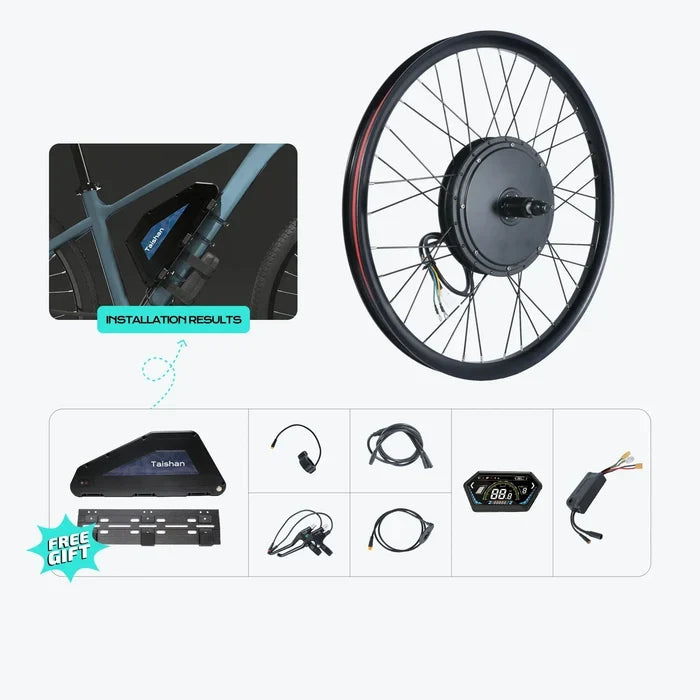
KirbEbike supplies installation accessories alongside its motor wheels and conversion kits, and its own guidance flags skipped torque arms and wrong dropout sizing as major risks. Identify the exact arm or plate shipping with your specific 1000W–4000W product — material, thickness, axle compatibility, one-arm/two-arm requirement, installation drawing and replacement route. The high-power kits it ships with include the 52V 2000W MTX, 60V 2500–3000W MTX and 72V 4000W kits.
Custom engineer-made torque plate
Designed around the exact frame and axle, using strong existing mounting points, a large contact area, and able to support very high measured torque. Limitations: needs accurate material selection, engineering review and precise manufacturing, must not introduce sharp frame loads, and cannot be judged by appearance.
KirbEbike High-Power Rear-Hub Kits
Torque-arm hardware ships with the high-power kits — matched to the motor, with the axle spec and installation drawing for your exact variant.
Post-Installation Safety Inspection
Before applying motor power
Confirm the axle is fully seated, the arm cannot rotate by hand, the mounting point is structurally suitable, axle nuts use verified torque values, rotor and drivetrain run freely, the cable is protected, and fasteners are marked so movement shows up later.
Initial low-load test
Only after an approved installation: support the driven wheel safely, check rotation at low power, confirm no cable movement, listen for contact and test the brake cutoffs. The widely repeated “hold the brake and blip the throttle” test deliberately applies high load while stationary — not a safe universal check on an installation you are still verifying.
First-ride and ongoing inspection
After the first rides, check for changed axle-nut witness marks, fresh metal around dropouts, paint cracking, arm or clamp movement, rotor rub, wheel misalignment and cable twisting. Set ongoing intervals by power level, off-road use, cargo load, regen, frame material and fastener type — not a generic mileage figure.
Warning Signs of Torque-Arm or Dropout Failure
What not to do after movement is found
Do not retighten and keep riding, add washers without diagnosis, fill damaged dropouts with adhesive, fit a second generic arm over the damage, file the dropout further, or exceed the specified axle-nut torque. Have it inspected by the kit supplier, a qualified mechanic or an engineer familiar with hub-motor loads.
Common Torque-Arm Installation Mistakes
Most failures trace back to a short list of avoidable errors:
- Selecting by wattage alone — measured torque, frame and controller settings decide the requirement.
- A loose axle plate — movement allows impact loading before the arm resists anything.
- Wrong mounting direction — some designs encourage axle ejection when reversed.
- Trusting a weak fender eyelet — a clean look does not prove structural capacity.
- Two low-quality arms assumed safe — equal load sharing is not guaranteed.
- Too many parts blocking the axle nut — inadequate thread engagement undermines wheel retention.
- Pinching the motor cable — damage can cause phase-wire shorts or system failure.
- Overtightening frame clamps — crushed tubing and stress risers lead to frame failure.
- Copying a torque value from another motor — different threads and washers create different preload.
- Raising controller current without re-checking the mechanics — tuning changes axle load even when the motor hasn’t changed.
Conclusion
A torque arm does not increase acceleration or motor torque — it controls the equal and opposite reaction torque acting on the axle. The correct setup depends on actual torque, controller current, axle dimensions, dropout strength, frame material, motor position, regen and the arm’s own design.
One properly engineered arm may be sufficient in some reviewed rear-motor installations. Two arms or a custom plate may be necessary for higher loads, reversing torque or weaker dropouts. Two generic arms are not automatically safer than one tested component, and no torque value, washer order or mounting direction should be copied across unrelated motors. If uncertain, send clear photographs and measurements to your kit supplier before applying motor power — and run your frame through the wheel and dropout fit check first.
FAQs
Do you need a torque arm for a 1000W ebike?
How do you set up an ebike torque arm?
Does a 2000W hub motor need two torque arms?
What is the torque of a 3000W hub motor?
What torque arm should be used for a 4000W hub motor?
Are two torque arms always better than one?
Does regenerative braking require a different torque arm?
Sources
- Grin Technologies — Torque Arms: designs, testing and installation guidance. ebikes.ca
- Grin Technologies — Futility of Motor Power Ratings (power vs torque). ebikes.ca
- Grin Technologies — Bike Compatibility (dropouts and hub-motor fit). ebikes.ca
- Park Tool — Wheel Removal and Installation. parktool.com
- Sheldon Brown — Bicycle Frame and Hub Spacing (cold-setting limits). sheldonbrown.com
- Cycling UK — EAPC regulations explained. cyclinguk.org
- UK Government — Electric bike rules (EAPC). gov.uk/electric-bike-rules