Het installeren van een e-bike ombouwset verandert uw gewone fiets in slechts 20-40 minuten in een elektrisch aangedreven machine – maar alleen als u veelvoorkomende installatiefouten vermijdt die de veiligheid, prestaties en levensduur van componenten in gevaar kunnen brengen.
Hoewel moderne ombouwsets van gerenommeerde fabrikanten zijn ontworpen voor eenvoudige doe-het-zelf-installatie, maken beginners vaak vermijdbare fouten die leiden tot slechte prestaties, voortijdige slijtage of zelfs gevaarlijke storingen.
Deze uitgebreide gids identificeert de meest kritieke installatiefouten en biedt beproefde oplossingen om ervoor te zorgen dat uw ombouw de eerste keer perfect slaagt.
Installatiesucces Begrijpen
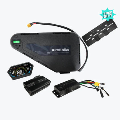
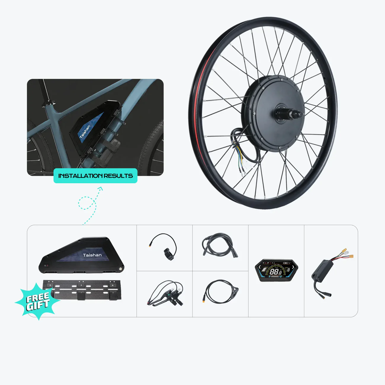
De beste ebike kitsystemen bevatten alles wat nodig is voor een succesvolle installatie: motor, accu, controller, display, sensoren, hardware, gereedschap en uitgebreide instructies. Installatiesucces hangt echter evenzeer af van het volgen van de juiste procedures en het vermijden van veelvoorkomende valkuilen die het systeem in gevaar brengen.
Waarom Installatiekwaliteit Belangrijk Is
Kritieke Pre-installatiefouten
Fout #1: Instructies Niet Volledig Lezen
De Fout: Veel installateurs springen direct naar de fysieke installatie zonder alle meegeleverde documentatie, video's en bronnen grondig te bekijken.
Waarom Het Problematisch Is:
- Gemiste kritieke voorbereidingsstappen
- Over het hoofd geziene compatibiliteitswaarschuwingen
- Essentiële veiligheidsprocedures overgeslagen
- Tijdverspilling door terug te moeten
- Risico op schade aan componenten
De Oplossing:
Voordat u componenten aanraakt:
- Bekijk de gehele installatievideo van begin tot eind
- Lees de complete handleiding
- Bekijk alle meegeleverde documentatie
- Controleer de website van de fabrikant op updates
- Word lid van een online community voor tips
Voorbereidingschecklist:
- ✓ Begrijp de volledige processtroom
- ✓ Identificeer alle componenten en hun functies
- ✓ Noteer eventuele fietsspecifieke overwegingen
- ✓ Verzamel al het benodigde gereedschap
- ✓ Zorg voor voldoende werkruimte
- ✓ Neem voldoende tijd zonder haast
Fout #2: Onvoldoende Voorbereiding van de Werkruimte
De Fout: Beginnen met de installatie op krappe, slecht verlichte of ongeschikte locaties zonder goede organisatie.
Gemaakte Problemen:
- Verloren kleine componenten
- Moeilijke toegang tot fietsgebieden
- Slechte zichtbaarheid voor verbindingen
- Frustratie en fouten
- Verlengde installatietijd
De Oplossing:
Ideale Werkruimte Inrichting:
- Schone, goed verlichte ruimte met voldoende plaats
- Fietsreparatiestandaard of veilige montage
- Vlakke ondergrond voor het organiseren van componenten
- Goede verlichting vanuit meerdere hoeken
- Alle gereedschap binnen handbereik
- Componentenbakjes of -containers voor kleine onderdelen
Organisatiestrategie:
- Leg alle kitcomponenten systematisch uit
- Controleer alles aan de hand van de paklijst
- Groepeer gerelateerde componenten
- Houd bevestigingsmiddelen geordend per type
- Houd de camera gereed voor documentatie
Fout #3: Verkeerde Keuze van Gereedschap
De Fout: Pogingen tot installatie met ongeschikt, inferieur of verkeerd formaat gereedschap.
Gevolgen:
- Afgestripte bevestigingsmiddelen
- Beschadigde componenten
- Afgeronde boutkoppen
- Onjuiste toepassing van koppel
- Risico op persoonlijk letsel
De Oplossing:
Benodigd Essentieel Gereedschap:
Naafmotor Installatie:
- Kwaliteits inbussleutelset (4 mm, 5 mm, 6 mm)
- Verstelbare moersleutel of pedaalsleutel (15 mm)
- Cassette-verwijderingsgereedschap (meegeleverd met kit)
- Kettingzweep (meegeleverd met kit)
- Bandenlichters
- Momentsleutel (aanbevolen)
- Trekbandjes en kniptang
- Elektrische tape
Middenmotor Installatie:
- Alle naafmotorgereedschap plus:
- Gereedschap voor het verwijderen van de trapas
- Cranksleutel
- Extra inbussleutels voor crankbouten
Kwaliteit van Gereedschap Is Belangrijk:
- Gebruik alleen gereedschap van het juiste formaat
- Vermijd afgerond of versleten gereedschap
- Investeer in kwaliteits-inbussleutels
- Overweeg een momentsleutel voor kritieke bevestigingsmiddelen
- Vervang beschadigd gereedschap onmiddellijk
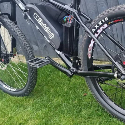
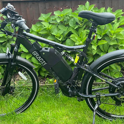
Fouten bij Motorinstallatie
![]()

Fout #4: Verkeerde Wieloriëntatie
De Fout: Het motorwiel achterstevoren of met verkeerd geleide kabels installeren.
Problemen die Dit Creëert:
- Motorkabel te kort om de controller te bereiken
- Remschijf aan de verkeerde kant
- Draairichting van de band incorrect
- Kabelspanning en mogelijke schade
- Moeilijke kabelgeleiding
De Oplossing:
Juiste Naafmotororiëntatie:
Voor achterwielmotoren:
- Motorkabel komt aan de niet-aangedreven zijde (linkerkant) uit
- Controleer de kabellengte vóór de volledige installatie
- Controleer of de remschijf overeenkomt met de remklauw
- Bevestig dat de cassette correct op de motor schroeft
Fout #5: Ontbrekende of Onjuist Geïnstalleerde Koppelarmen
De Fout: Koppelarmen volledig weglaten of onjuist installeren - één van de gevaarlijkste installatiefouten.
Waarom Dit Kritiek Is:
Koppelarmen voorkomen rotatie van de motoras onder kracht door:
- Motorkoppel naar het frame over te brengen
- Schade aan de uitvaleinden te voorkomen
- De integriteit van het frame te beschermen
- Een veilige werking te garanderen
Risico op Frameschade:
- Aluminium frames zijn bijzonder kwetsbaar
- Uitvaleinden kunnen barsten of vervormen
- Framebreuk mogelijk onder kracht
- Gevaarlijke plotselinge defecten
- Dure framevervanging
De Oplossing:
Juiste Installatie van Koppelarmen:
Minimumvereisten:
- Eén koppelarm voor motoren onder 750W
- Twee koppelarmen voor motoren van 1000W en hoger
- Beide zijden voor krachtige systemen (2000W+)
Installatieprocedure:
- Reinig het uitvalgebied grondig
- Plaats de koppelarm vlak tegen het uitvaleinde
- Steek door de as
- Verbind met het frame of de vork
- Draai alle bevestigingsmiddelen vast volgens specificatie
- Controleer of er geen beweging mogelijk is
- Controleer opnieuw na de eerste rit
Fout #6: Onjuist Aandraaien van de As
De Fout: Te strak of te los aandraaien van de asmoeren van het motorwiel.
Gevolgen:
Te strak aandraaien:
- Beschadigde schroefdraad van het uitvaleinde
- Verbogen as
- Geplette lagers
- Moeilijke verwijdering
- Frame schade
Correcte Aandraaiprocedure:
De elektrische fiets kit batterij systemen bevatten specifieke aanhaalmomenten:
Algemene Richtlijnen:
- Gebruik geleidelijke, gelijkmatige druk
- Draai de moeren afwisselend aan (links-rechts-links-rechts)
- Controleer de aanhaalmomenten van de fabrikant
- Gebruik een momentsleutel voor precisie
- Controleer of het wiel gecentreerd is in het frame/de vork
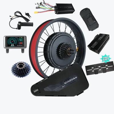
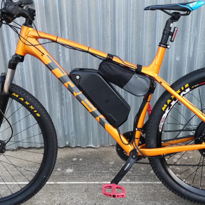
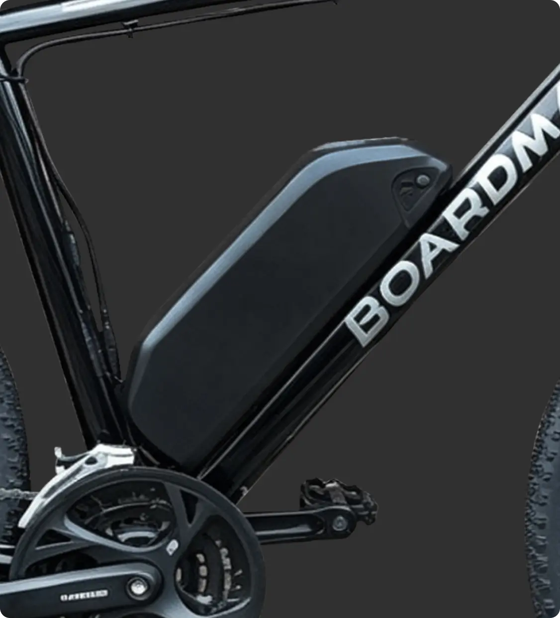
Fouten bij de Installatie van Batterij en Controller
![]()

Fout #7: Slechte Bevestigingslocatie Batterij
De Fout: De accu monteren op een plaats waar deze het rijden hindert, onbalans creëert of risico op schade oplevert.
Gemaakte Problemen:
- Kniehinder tijdens het trappen
- Slechte gewichtsverdeling
- Kabelspanning
- Moeilijke verwijdering van de accu
- Verhoogd risico op schade
De Oplossing:
Optimale Plaatsing van de Accu:
Montage op de Onderbuis (Meest Voorkomend):
- Laag en centraal zwaartepunt
- Gemakkelijke toegang voor verwijdering
- Beschermd tegen stoten
- Rechte kabelgeleiding
- Heeft geen invloed op het rijden
Beste Praktijken voor Installatie:
- Gebruik alle meegeleverde bevestigingsbouten
- Controleer de uitlijning van de bidonhoudergaten
- Controleer de pedaalvrijheid (vooral bij volledig stuuruitslag)
- Zorg ervoor dat de kabel zonder spanning kan reiken
Controleer het gemak van het verwijderen/plaatsen van de accupack
Controleer of het vergrendelingsmechanisme functioneert
Fout #8: Kabelbeheer negeren
De fout: Kabels los laten, niet vastzetten of zo leggen dat ze kunnen haken, schuren of beschadigd raken.
Gevolgen:
- Kabelslijtage door schuren
- Haken aan obstakels
- Waterindringing bij aansluitingen
- Onprofessionele uitstraling
- Potentiële kortsluiting
- Veiligheidsrisico's
De oplossing:
Professioneel kabelbeheer:
Legprincipes:
- Volg de natuurlijke lijnen van het frame
- Vermijd bewegende delen (cranks, wielen)
- Voorkom schuren aan de band
- Houd uit de buurt van warmtebronnen
- Zorg voor voldoende ruimte voor het stuur
- Bescherm tegen waterspatten
Fout #9: Omgekeerde motorkabelaansluitingen
De fout: Motorfasedraden in de verkeerde volgorde aansluiten, waardoor de motor achteruit draait of inefficiënt werkt.
Symptomen:
- Motor draait in tegengestelde richting
- Verminderd vermogen
- Controllerfouten
- Abnormale geluiden
- Slechte prestaties
De oplossing:
Juiste aansluitprocedure:
De meeste moderne systemen gebruiken gecodeerde connectoren die onjuiste aansluiting voorkomen, maar als er problemen optreden:
Diagnose:
- Zet het systeem aan en test de gashendel
- Observeer de draairichting van het wiel
- Controleer het display op foutcodes
- Controleer op een soepele werking
Correctie (indien nodig):
- Ontkoppel de motorfasedraden
- Wissel twee van de drie fasedraden om
- Test de werking
- Indien nog steeds incorrect, probeer een andere combinatie
- Bevestig correct als het goed is
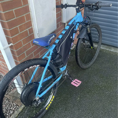
Fouten in display- en besturingssystemen
![]()

Fout #10: Onjuiste sensorinstallatie
De fout: Het onjuist installeren of uitlijnen van de pedaalondersteuningssensor (PAS) of het niet goed bevestigen ervan.
Problemen die dit veroorzaakt:
- Geen pedaalondersteuningsfunctie
- Inconsistente assistentieactivering
- Vertraagde motorrespons
- Assistentie blijft constant aan
- Voortijdige slijtage van onderdelen
De oplossing:
Installatie van cadanssensor:
Schijf-type PAS:
- Bevestig de sensorbeugel aan de linkerkant van de crank
- Plaats de sensorkop dicht bij de trapas
- Installeer de sensorschijf op de crankarm of pedaalas
- Lijn uit met een opening van 2-3 mm tussen schijf en sensor
- Zet alle bevestigingsmiddelen vast
- Test rotatie - geen wrijving
Magneet-type PAS:
- Installeer de sensor op de liggende achtervork
- Bevestig de magneet aan de crankarm
- Lijn uit voor de juiste opening (meestal 5 mm)
- Controleer de speling gedurende de gehele pedaalrotatie
- Test de sensordetectie
Fout #11: Problemen met displaymontage
De fout: Het display zo monteren dat het moeilijk af te lezen is, de bediening hindert of kwetsbaar is voor beschadiging.
Gevolgen:
- Slecht zicht tijdens het rijden
- Moeilijke toegang tot knoppen
- Kabelspanning
- Botsing met knieën
- Blootstelling aan weersinvloeden
De oplossing:
Optimale displayplaatsing:
Positiecriteria:
- Gemakkelijk zichtbaar tijdens het rijden
- Knoppen toegankelijk zonder de hand te verplaatsen
- Interfereert niet met rem-/schakelhendels
- Beschermd tegen directe impact
- Kabel reikt zonder spanning
- Veilige montage
Fout #12: Het weglaten van de remsensor
De fout: Het nalaten om remonderbrekingssensoren te installeren of deze verkeerd te installeren – een ernstig veiligheidsprobleem.
Veiligheidsrisico: De motor blijft draaien bij het remmen, wat veroorzaakt:
- Langere remafstanden
- Verlies van controle
- Overbelasting van het remsysteem
- Ongevalsrisico
- Wettelijke aansprakelijkheid
De oplossing:
Verplichte installatie van remsensoren:
Installatieprocedure:
- Verwijder bestaande remhendels (indien vervangen)
- Installeer nieuwe hendels met geïntegreerde sensoren
- Sluit remsensorkabels aan op de controller
- Pas de hendelafstand aan voor comfort
- Leg de kabels netjes
- Test uitvoerig voordat u gaat rijden
Verificatietesten:
- Zet het systeem aan
- Activeer de gashendel of pedaalondersteuning
- Trek de remhendel in
- De motor moet onmiddellijk uitschakelen
- Test zowel voor als achter
- Controleer op snelle respons
Kritische veiligheidscontrole:
- Test eerst op lage snelheid
- Controleer op onmiddellijke motoruitschakeling
- Controleer beide remmen onafhankelijk
- Test in verschillende assistentieniveaus
- Bevestig consistente werking
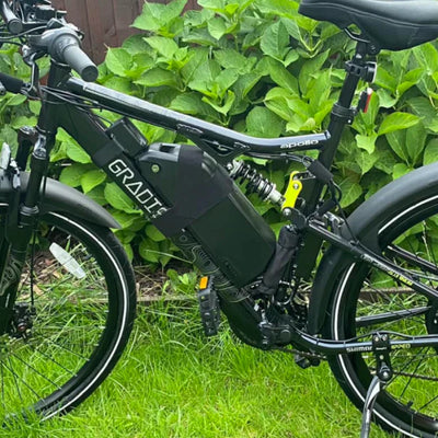
Fouten in het elektrische systeem
![]()

Fout #13: Waterdichtheid negeren
De fout: Elektrische verbindingen niet goed afdichten of componenten blootstellen aan waterindringing.
Gevolgen op lange termijn:
- Corrosie van verbindingen
- Intermitterende storingen
- Kortsluiting
- Schade aan onderdelen
- Brandgevaar
De oplossing:
Beste praktijken voor waterdicht maken:
Verbindingsbescherming:
- Zorg ervoor dat alle connectoren volledig zijn aangesloten
- Controleer of de rubberen afdichtingen goed zitten
- Breng diëlektrisch vet aan op de verbindingen
- Gebruik isolatietape op verdachte plaatsen
- Plaats connectoren uit de buurt van directe spetters
- Leid kabels zo dat water wordt afgevoerd
Plaatsing van componenten:
- Controller op een beschermde locatie
- Accuconnectoren indien mogelijk naar beneden gericht
- Display schuin geplaatst om water af te voeren
- Sensoren beschermd tegen directe spetters
Onderhoud:
- Inspecteer verbindingen regelmatig
- Reinig en breng jaarlijks diëlektrisch vet opnieuw aan
- Vervang beschadigde connectordichtingen
- Controleer op corrosie
- Pak eventuele waterindringing onmiddellijk aan
Controlelijst voor test voor de rit:
|
Test
|
Procedure
|
Slaagcriteria
|
|
Aanzetten
|
Schakel de batterij en het display in
|
Display brandt, geen fouten
|
|
Gashendel
|
Hef het achterwiel op, test de gashendel
|
Vloeiende acceleratie, juiste richting
|
|
Remonderbrekers
|
Activeer de motor, trek de remmen in
|
Onmiddellijke motoruitschakeling aan beide zijden
|
|
Pedaalondersteuning
|
Trap vooruit in elk niveau
|
Vloeiende inschakeling, passend vermogen
|
|
Displayfuncties
|
Controleer alle knoppen en menu's
|
Alle functies reageren correct
|
|
Batterijstand
|
Controleer de weergave van het laadniveau
|
Nauwkeurige indicatie
|
|
Verlichting
|
Test koplamp en remlicht
|
Juiste werking indien uitgerust
|
|
Sensoren
|
Controleer alle sensorfuncties
|
Correcte detectie en respons
|
Initiële rijtest:
- Begin in een veilige, open omgeving
- Test eerst lage ondersteuningsniveaus
- Controleer de effectiviteit van het remmen
- Controleer wijzigingen in het rijgedrag
- Test alle ondersteuningsniveaus progressief
- Controleer de bereiksschatting
- Controleer op ongebruikelijke geluiden
- Houd het batterijverbruik in de gaten
Fout #16: Negeer koppel specificaties
De fout: De juiste strakheid raden in plaats van de gespecificeerde koppelwaarden te volgen.
Onderdeelrisico:
Kritische bevestigingsmiddelen:
- Motorasmoeren
- Koppelarmbouten
- Bevestigingsbouten accu
- Crankschroeven (middenmotor)
- Trapas (middenmotor)
- Cassette borgring
De oplossing:
Richtlijnen voor koppelspecificaties:
Hoewel specifieke waarden per onderdeel verschillen:
Algemene bereiken:
- Motorasmoeren: typisch 35-40 Nm
- Koppelarmbouten: typisch 15-20 Nm
- Accubouten: typisch 5-8 Nm
- Crankschroeven: typisch 35-40 Nm
- Cassette borgring: typisch 40 Nm
Beste praktijken:
- Investeer in een kwalitatieve momentsleutel
- Volg exact de specificaties van de fabrikant
- Draai in de juiste volgorde aan
- Controleer opnieuw na de eerste 50 km
- Documenteer alle toegepaste koppelwaarden
Conclusie
Door deze veelvoorkomende installatiefouten te vermijden, zorgt u ervoor dat uw e-bike-conversie jarenlang veilige, betrouwbare, krachtige elektrische ondersteuning biedt. De installatie van een 20 minuten durende naafmotor of 30-40 minuten durende middenmotor wordt eenvoudig als u zich goed voorbereidt, de instructies zorgvuldig volgt en de tijd neemt om elke stap correct uit te voeren.
Kwaliteit elektrische middenmotor ombouwsets van gerenommeerde fabrikanten bevatten alles wat nodig is voor succes, maar de kwaliteit van de installatie bepaalt de daadwerkelijke prestaties en levensduur.
Veelgestelde vragen
Wat is de meest kritieke fout om te vermijden bij het installeren van een e-bike ombouwset?
Het ontbreken of onjuist installeren van koppelarmen is de gevaarlijkste fout, met risico op frameschade en plotseling falen. Installeer altijd minimaal één koppelarm voor motoren onder de 750 W, twee voor systemen van 1000 W of meer. Controleer of ze goed vastzitten en niet kunnen draaien – dit ene onderdeel voorkomt duizenden euro's aan frameschade en ernstige veiligheidsrisico's.
Hoe strak moeten motorasmoeren worden aangedraaid?
Volg de koppel specificaties van de fabrikant (doorgaans 35-40 Nm) met behulp van een momentsleutel. Te strak aandraaien beschadigt de dropouts en lagers, terwijl te los aandraaien beweging veroorzaakt met remproblemen en veiligheidsrisico's tot gevolg. Draai geleidelijk afwisselend aan beide zijden aan, controleer de centrering van het wiel en controleer opnieuw na 50 km rijden voor optimale veiligheid.
Moet ik echt remonderbrekingssensoren installeren?
Absoluut — remsensoren zijn verplichte veiligheidscomponenten die de motor onmiddellijk uitschakelen bij het remmen. Zonder deze sensoren blijft de motor draaien tijdens het remmen, waardoor de remafstand drastisch toeneemt en gevaarlijke situaties van controleverlies ontstaan. Test beide remsensoren grondig voor het rijden om de onmiddellijke motoruitschakeling te controleren.
Wat is de juiste afstand voor pedaalondersteuningssensoren?
Houd een afstand van 2-3 mm aan tussen de sensor kop van de schijf-type PAS-sensor en de sensor schijf. Te dichtbij veroorzaakt wrijving en sensorschade, te ver weg voorkomt detectie en schakelt de pedaalondersteuning uit. Controleer de speling gedurende de volledige pedaalrotatie, bevestig alle montageonderdelen en test de sensorrespons voordat u gaat rijden.
Hoe weet ik of mijn kabels correct zijn geleid?
Correcte kabelgeleiding volgt de natuurlijke lijnen van het frame, vermijdt bewegende delen (wielen, cranks), voorkomt wrijving op banden, zorgt voor voldoende stuuruitslag en bevestigt elke 15-20 cm met kabelbinders. Controleer of er geen spanning op de verbindingen staat, of er bescherming is tegen opspattend water en of het er professioneel uitziet. Test de volledige stuurbeweging voor het rijden.
Moet ik het systeem testen vóór mijn eerste rit?
Uitgebreide tests vóór de rit zijn essentieel: til het achterwiel op en test de gashendel op correcte rotatie, controleer of beide remsensoren de motor onmiddellijk uitschakelen, test alle pedaalondersteuningsniveaus, controleer de displayfuncties, zorg ervoor dat er geen ongebruikelijke geluiden zijn en controleer of de batterijmetingen nauwkeurig zijn. De eerste rit moet plaatsvinden in een veilige, verkeersvrije omgeving, waarbij geleidelijk wordt getest.
Wat moet ik doen als ik een fout maak tijdens de installatie?
Stop onmiddellijk, forceer niets en raadpleeg de instructies of video's. Demonteer terug naar de laatst bekende goede staat, identificeer de fout, corrigeer deze correct en ga systematisch te werk. Neem contact op met de fabrikantondersteuning als u twijfelt - beter vragen dan onderdelen beschadigen of veiligheidsrisico's creëren. Documenteer problemen voor toekomstige referentie.
: invalid url input)
usmile
Liquid error (snippets/blog-best-product line 36): product form must be given a product
Liquid error (snippets/blog-best-product line 59): product form must be given a product